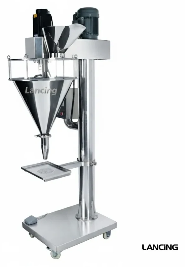
 Bench / compact
Semi-automatic auger fillers
Compact auger filling for short runs, product trials, smaller batches and operator-presented jars, bottles, tubs or pouches.
View routeConveyor-fed auger filling routes for powders and dry products where repeatable dosing, container handling and line integration are required.
Automatic auger fillers suit production where jars, bottles or tubs need repeatable filling on a conveyor, often with downstream capping, sealing, labelling and coding. The machine route should be built around container stability and line control.
The filler, conveyor and closure route should be scoped together so one stage does not limit the line.
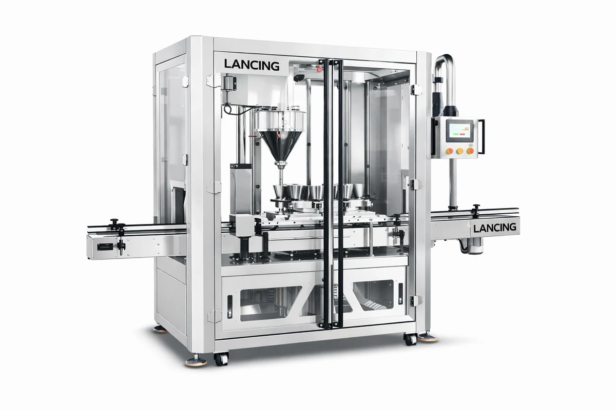
Automatic auger fillers are specified around product feed, container handling, guarding, filling accuracy, cleaning access and downstream integration.
Powders may aerate, bridge, dust or settle after filling. Automatic lines should allow for product behaviour between dosing and closing, especially where headspace, cap torque, induction sealing or checkweighing are part of the finished pack.
Automatic auger filling is strongest when each line stage is specified as part of the same production route.
Bench / compact
Compact auger filling for short runs, product trials, smaller batches and operator-presented jars, bottles, tubs or pouches.
View route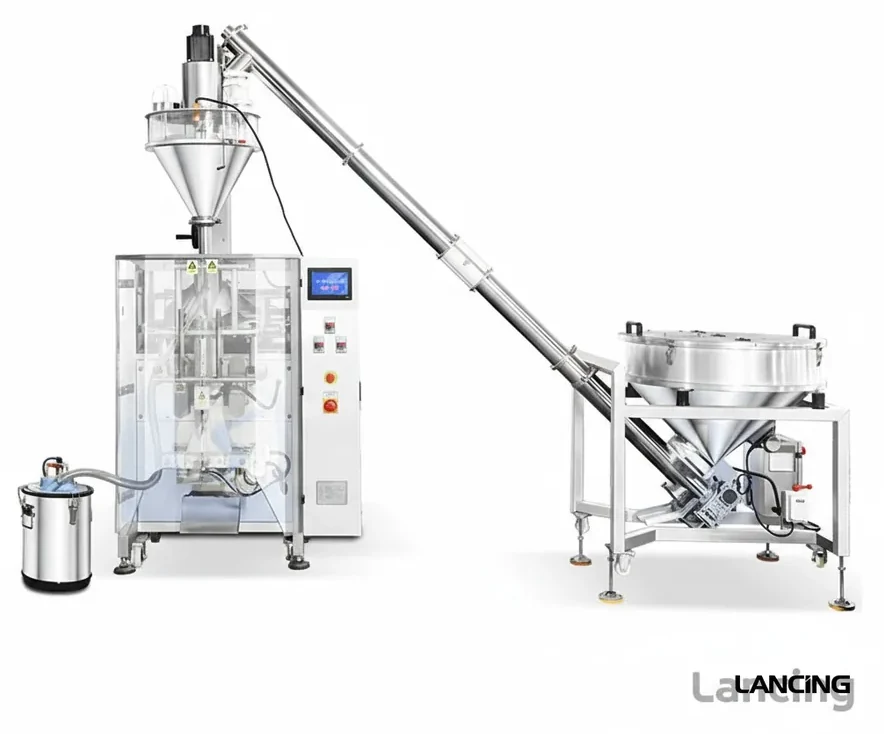 Bagging / roll film
Auger dosing integrated with vertical form fill seal bagging for powder pouches, sachets and formed bags from roll film.
View route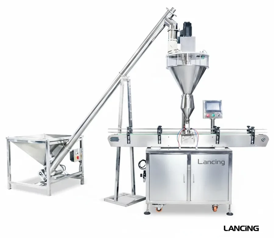 Line planning
Product feed, filling, settling, capping, sealing, labelling, coding and checking planned as one dry-product route.
View route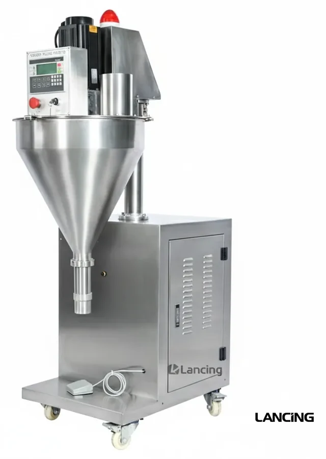 Route
Route
General powder dosing where flow, dust and fill consistency decide the auger route.
View route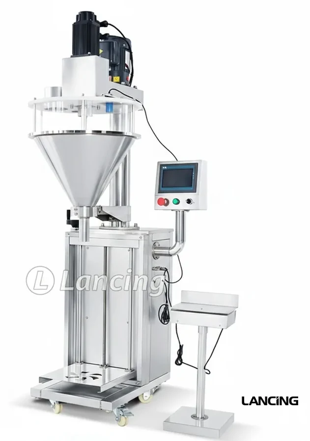 Route
Route
Dry-powder filling for sports nutrition, supplement tubs, pouches and jars.
View route
Route
Practical auger-filling considerations for detergent, cleaning and industrial powders.
View route
Route
Rigid-container auger filling routes for wide-neck jars, bottles, tubs and pots.
View routeAuger fillers are normally used for powders and some fine granules where controlled screw dosing gives a more suitable route than a pump, cup filler or basic gravity feed.
Yes, but the container handling and discharge setup changes. Rigid containers, premade pouches, VFFS bags and sachets all need different presentation and sealing arrangements.
Send the product name, sample behaviour, fill weight range, pack dimensions, target output, accuracy requirement, available space and any sealing, capping, labelling or coding steps.
Send the product, pack format, target fill weight and required output so Lancing can suggest the most suitable auger filler route.
The documented LU-FM4A project basis used three independently driven auger stations for a nominal 50 g powder dose into an approved bottle. The final screw, nozzle, powder conditioning and line settings remain subject to product and pack trials.
| Machine type | Automatic three-head servo auger powder filling machine. |
|---|---|
| Published filling range | 50–300 g, customised around the approved nominal 50 g application. |
| Dosing heads | Three servo-controlled auger heads operating in parallel. |
| Powder presentation | Three hoppers with agitation or conditioning arrangements selected after product testing. |
| Tooling | Custom screw and filling-nozzle diameter and profile to suit the powder and bottle neck. |
| Controls | Industrial PLC and colour HMI with recipes, counters, alarms and manual controls; photoelectric bottle sensing with no-bottle/no-fill logic. |
| Accuracy basis | Final fill repeatability and tolerance are to be established during sample trials and factory acceptance testing using the customer powder, bottle and agreed sampling plan. |
| Output basis | Documented practical integrated-line target of 25–35 bottles/min for the nominal 50 g project, subject to trials and downstream line performance. |
First-party machinery footage showing an auger filling head operating over a conveyed bottle line. It is application footage rather than a performance test for a named model.
Video is useful for confirming the mechanical sequence, but it does not replace a measured trial. A factory test should pair the operating footage with the approved powder and bottle, consecutive fill-weight records, the stated line speed, dust observations and the agreed acceptance criteria.
In the documented project, the auger filler was specified as part of a fill, screw-cap and front/back labelling line. That means bottle stability, conveyor transitions, cap application, label handling and shared interlocks must be reviewed alongside the dose. The sustained line output is the useful measure, not an isolated auger cycle.
Close-fitting custom nozzles and dust-control provisions at the filling head were included in the documented basis, while central extraction was not. If the powder requires extraction, enclosure or hazardous-area controls, those requirements must be identified from product data and competent assessment before the line is finalised.
Three independently driven heads can fill several indexed containers during each machine cycle, increasing capacity without forcing one head to operate at an excessive cycle rate.
No. The documented LU-FM4A range is 50–300 g, but the final screw, nozzle, hopper arrangement, fill height, speed and repeatability must be established with the approved powder and bottle during trials and factory acceptance testing.
The filling nozzle diameter and anti-spill profile are developed around the bottle opening and powder behaviour. Container guides and locating parts also need to hold the pack steadily under the filling heads.
The documented LU-FM4A configuration included close-fitting custom nozzles and dust-control provisions at the head, while central extraction was not included. Any extraction connection or enclosure must be defined for the actual powder and site.
Yes, where the line is engineered as an integrated project. Product sensors, conveyor transitions, machine-ready signals, emergency-stop interfaces and accumulation need to be agreed across the supplied equipment.
The agreed trial should verify powder feed, container handling, dose results against the sampling plan, output under the stated conditions, dust behaviour, alarms and interlocks, restart after stops and the approved pack transfer to downstream equipment.
Send representative powder, bottle and closure samples, the target dose and sustained output so Lancing can define the trial and integrated line basis.